3-D REVOLUTION PRODUCTIONS
3D, 4D & 5D Animation Production & Consultancy
Since 1999
Tel. +353 858124775
info @ the3drevolution.com
|
3-D REVOLUTION PRODUCTIONS
3D, 4D & 5D Animation Production & Consultancy |
Tel. +353 858124775 info @ the3drevolution.com |
| ▶SERVICES | SHOWREEL | CLIENTS | 3D INFORMATION | CONTACT |
|
3D Stereoscopic film production and Consultancy |
|
|
Our services include full 3D and 4D film production, post-production assistance, consultation and supervision. Our 2013 Shoreel:
|
|
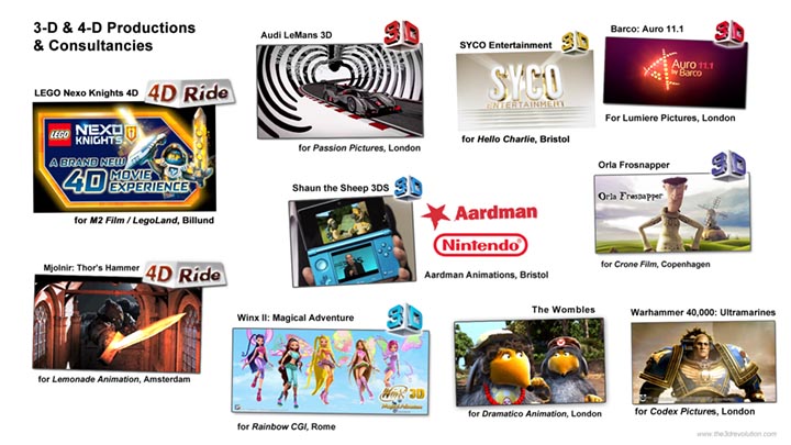
3D STEREOSCOPIC FILM PRODUCTION AND CONSULTANCY Alexander Lentjes offers consultancy, production supervision, Quality Checking and hands-on production assistance if and when required, besides giving workshops and masterclasses at world-class 3D and future media events. Some of the projects and clients work for:
|
|
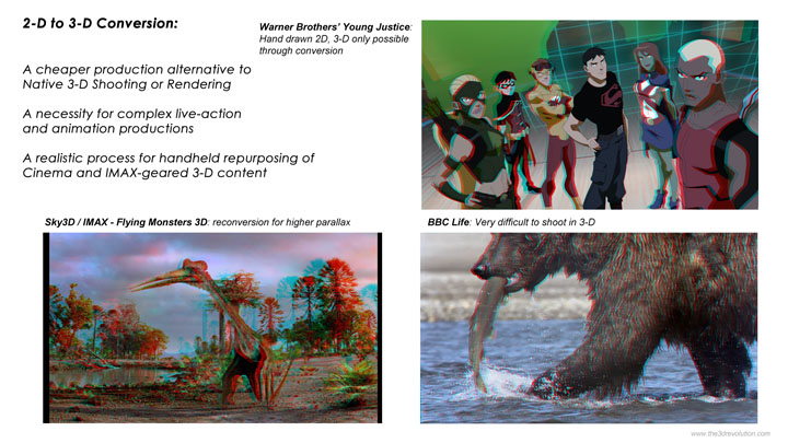
2D TO 3D FILM & TELEVISON CONVERSION 2-D to 3-D conversion offers the following advantages for live-action and animated content alike:
Large volume conversion like full television series 3D conversion is now a realistic budget option. Contact 3-D Revolution Productions to inquire about conversion options and costs.
|
|
2D & 3D PRE-PRODUCTION, PRODUCTION & POST-PRODUCTION
|
Top |